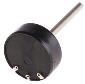
A control setting is only useful when an operator can return to it confidently. In test rigs, teaching equipment and service instruments, small changes in resistance may affect a reference voltage or the response of a circuit. A Wirewound Potentiometer offers a direct mechanical adjustment, but repeatable results depend on thoughtful calibration rather than the knob alone.
The Wirewound Potentiometer, RS PRO P40 part 842-7090, is a 10 kΩ, single-turn rotary component with a linear taper, a 3 W power rating and ±10% resistance tolerance. Its specified mechanical rotation is 285°. These characteristics can suit manually adjusted instrument circuits, although they do not make the component a precision-calibrated control by themselves.
Why Does Repeatability Matter More Than a Knob Position?
Consider an instrument with a front-panel setting marked halfway. Two operators may align the pointer with the same marking yet obtain slightly different electrical results because of component tolerance, connected circuitry and reading technique.
The answer is to define the setting by its measured output. A label provides a convenient reference, while the calibration record establishes what that reference means under controlled conditions.
What Does a Linear Taper Actually Guarantee?
A linear potentiometer is designed so resistance changes approximately with angular movement. However, a wirewound element consists of individual wire turns, and movement of the wiper can produce small resistance steps.
A 285° rotation also leaves a limited physical adjustment range. For fine calibration, compare the required resolution with the available travel before finalising the component.
Where Can Manual Adjustment Help a Test Bench?
An adjustable reference may be useful in an educational circuit, analogue demonstration or a simple equipment setup. A technician can vary a signal while watching how the connected system responds.
For example, Bench Power Supplies can energise a prototype at the required voltage, while Function Generators & Counters can provide known test signals. In each case, the potentiometer should control an appropriately designed input, not replace the instrument’s own electrical protection.
How Should You Prepare a Calibration Worksheet?
Before touching the knob, decide which output quantity matters and how accurately it must be measured. Record the supply conditions, load, instrument identification and environmental factors that could influence the result.
A practical worksheet can include:
- The desired output and acceptable tolerance.
- Starting and ending control positions.
- The reference instrument and its calibration status.
- Results at several points across the usable travel.
- Observations of jumps, drift or inconsistent behaviour.
- The date, technician and approved final setting.
This turns a subjective adjustment into a procedure another person can reproduce.
How Do You Check the Entire Adjustment Range?
Begin with the equipment isolated and follow the circuit’s safe test procedure. Confirm the expected terminal functions from the approved drawing. Then energise only when the assembly is ready for a controlled test.
Move the control in small increments and record the corresponding voltage or other output. Suitable Test Leads help establish reliable connections, while Oscilloscopes can reveal fluctuations or unwanted noise that a steady numerical reading might not show.
Why Should You Measure With the Actual Load Connected?
A potentiometer used as a voltage divider may produce one voltage with a high-impedance meter and another after a circuit loads its wiper. The connected input therefore needs to be considered in the design.
Measurements made only with an unloaded circuit can be misleading. Test under realistic operating conditions, and add buffering where the circuit requires it rather than demanding an unrealistic performance level from a passive component.
What Causes a Setting to Shift Between Sessions?
A reference can drift because of temperature changes, poor contacts, changes in supply voltage or movement of the control. Mechanical vibration and repeated handling can also expose weaknesses in panel mounting.
Do not attribute every unstable reading to the potentiometer. First compare the supply, connected load and measuring instrument with the conditions recorded during calibration.
Can a Single-Turn Control Replace a Fine Trimmer?
Not always. Trimmer Resistors are often better suited to infrequent, internal adjustments, while a panel-mounted rotary control makes intentional operator changes easier. Both must be selected for the required stability and resolution.
When accuracy requirements become especially tight, consider whether a multi-turn component or digital calibration method is a better solution than increasing the markings around a short-turn knob.
When a technician adjusts the reference interactively, Panel Meters can display the electrical result next to the shaft. This allows a measured value, rather than a pointer marking, to guide the setting.
How Can Panel Design Prevent Operator Error?
A control should be easy to identify and difficult to adjust accidentally. Use a readable scale, a clear direction indicator and enough clearance for hands or tools. Avoid ambiguous labels such as “normal” unless the corresponding measured value is documented.
Choose markings that are legible under normal lighting and keep the operating instructions nearby. A clearly positioned indicator reduces the temptation to rely solely on an approximate knob position.
What Should Happen After Calibration?
Once the target is reached, confirm it by approaching the setting from the same direction used in the documented procedure. Repeat measurements to check consistency, and record any required settling time.
Apply an approved tamper indicator if accidental adjustment would disrupt the equipment. Store the calibration results with the circuit documentation and revisit them after servicing, component replacement or unexplained changes in output.
How Do You Choose a Suitable Potentiometer for the Job?
Start with the intended input resistance, available electrical power, expected adjustment frequency and acceptable resolution. For the RS PRO 842-7090, confirm its 10 kΩ value, linear characteristic and physical dimensions against the manufacturer’s current drawing before specifying panel hardware.
When comparing Potentiometers, look beyond nominal resistance. A documented calibration method, appropriate loading and clear feedback are what turn a manual adjustment into a dependable instrument setting.