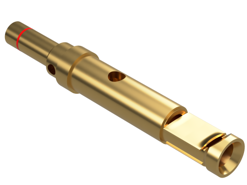
D Sub Contacts
Introduction
D Sub Contacts are essential conductive components used inside D-sub connectors to transfer electrical signals, data, and power between cables, circuit boards, machines, and control devices. Their small size can make them seem simple, but their design has a major influence on connection accuracy, equipment safety, signal stability, and long-term reliability.
Different systems place different demands on their contacts. A contact used in laboratory equipment may prioritise low resistance and signal precision, while one installed in industrial machinery may need greater resistance to vibration, temperature changes, and mechanical stress. Choosing the correct D Sub Contacts requires an understanding of connector compatibility, electrical ratings, wire characteristics, termination styles, and operating conditions.
Why Are D Sub Contacts Important in Electronic Design?
A connector may appear secure externally while still containing weak or unsuitable internal contacts. Since every electrical path passes through the contact interface, poor contact performance can affect the entire system.
Well-selected contacts help provide:
- Stable electrical continuity
- Reliable signal transmission
- Controlled contact resistance
- Secure conductor retention
- Reduced risk of intermittent faults
- Longer connector service life
- Easier maintenance and replacement
In communication and measurement circuits, even a brief interruption can cause corrupted data or inaccurate readings. In power circuits, excessive resistance may create heat and reduce efficiency. The contact must therefore support both the electrical and mechanical requirements of the application.
How Are D Sub Contacts Constructed?
Most D Sub Contacts include a mating section, retention area, and termination section. Each part performs a different function within the connector assembly.
The mating section forms the electrical interface between the pin and socket. The retention area locks the contact inside the connector insert. The termination section connects the contact to a wire, cable, or printed circuit board.
Manufacturers carefully control contact dimensions to ensure correct alignment and consistent mating pressure. Small dimensional differences can affect insertion depth, retention strength, and compatibility with the connector housing.
Understanding Pin and Socket Contact Functions
Pin contacts are usually fitted on one side of the connector, while socket contacts are installed on the corresponding side. When the connector halves are joined, each pin enters a socket and completes an individual circuit.
The socket contains flexible elements that maintain pressure against the pin. This pressure must remain stable during repeated connection cycles. If it becomes too weak, the circuit may develop unstable resistance. If it is excessive, mating force and surface wear may increase.
Correct pin and socket pairing supports:
- Smooth connector engagement
- Consistent electrical contact
- Accurate circuit alignment
- Reduced risk of bent contacts
- Predictable mating durability
Connector halves should never be forced together because misalignment can permanently damage the contacts.
Which Termination Method Should Be Selected?
Crimp Contacts for Production and Field Wiring
Crimp D Sub Contacts are widely used where speed, repeatability, and mechanical strength are important. The stripped conductor is inserted into the contact barrel, and a calibrated tool compresses the barrel around the wire.
A successful crimp creates a low-resistance joint without solder or heat. It is particularly suitable for cable assemblies exposed to vibration or regular maintenance.
Crimp quality depends on:
- Correct conductor size
- Accurate stripping length
- Compatible dies and locators
- Full wire insertion
- Proper compression force
- Inspection after termination
Solder Contacts for Custom Assemblies
Solder contacts are useful for prototypes, repairs, custom cables, and low-volume manufacturing. They allow individual wires to be connected using conventional soldering techniques.
The soldering process must be controlled carefully. Excessive heat can damage wire insulation, soften plastic inserts, or allow solder to enter the mating area. The joint should be clean, secure, and free from excess material.
PCB Contacts for Equipment Integration
Printed circuit board contacts allow a D-sub connector to be mounted directly onto electronic hardware. Straight contacts are commonly used for vertical mounting, while right-angle versions support horizontal arrangements.
Board-mounted designs should include suitable mechanical support so repeated mating force does not place excessive stress on solder joints.
How Do Electrical Ratings Affect Contact Choice?
Every contact has electrical limits based on its material, size, construction, and surrounding connector arrangement. Current capacity is especially important because overloaded contacts can produce unwanted temperature rise.
Voltage rating also matters, particularly where contacts are positioned close together. The complete connector system must provide sufficient spacing and insulation for the application.
Selection should consider:
- Maximum operating current
- Working voltage
- Contact resistance
- Insulation requirements
- Temperature rise
- Signal frequency
- Circuit sensitivity
Low-current signal circuits may focus on surface quality and resistance stability. Power circuits require greater attention to conductor size, heat management, and secure termination.
Why Does Contact Plating Matter?
Contact plating protects the conductive base material and improves mating performance. Different finishes provide different combinations of conductivity, corrosion resistance, durability, and cost.
Gold plating is often selected for low-level signals, frequent mating, or environments where corrosion could affect performance. Tin plating may be suitable for general-purpose applications with fewer mating cycles. Nickel is frequently used beneath the final finish as a barrier and support layer.
The most suitable plating depends on:
- Expected mating frequency
- Signal sensitivity
- Environmental exposure
- Required service life
- Budget limitations
- Maintenance accessibility
Mixing incompatible contact finishes may increase wear or corrosion, so mating surfaces should be chosen as a compatible pair.
Where Are D Sub Contacts Commonly Installed?
D Sub Contacts are used in a wide variety of commercial, industrial, and specialised equipment. Their established format, secure housing, and flexible termination options make them suitable for both legacy and modern systems.
Common applications include:
- Industrial control panels
- Programmable automation equipment
- Test and measurement instruments
- Computer communication interfaces
- Medical monitoring systems
- Railway electronics
- Aerospace equipment
- Robotics and motion control
- Security and surveillance systems
- Laboratory devices
Some applications use standard signal layouts, while others combine signal, power, coaxial, or high-voltage contacts in one connector body.
How Can Assembly Errors Be Avoided?
Many connection failures begin during assembly. Incorrect wire preparation, unsuitable tools, damaged contact surfaces, or incomplete insertion can reduce performance before the connector enters service.
Good assembly practices include:
- Confirming the cavity layout before wiring
- Using the specified insertion tool
- Avoiding contact with plated mating surfaces
- Checking that each contact locks into position
- Applying suitable cable strain relief
- Testing continuity before installation
- Inspecting for bent or recessed contacts
- Keeping unused components protected from contamination
Clear wire identification also reduces the risk of circuits being inserted into the wrong cavities.
Testing and Quality Control
Completed connector assemblies should be tested according to their intended use. A basic continuity test confirms that each circuit is connected, but demanding systems may require additional checks.
Testing may include:
- Contact resistance measurement
- Insulation resistance testing
- Short-circuit detection
- Pull-force testing
- Mating and unmating checks
- Vibration testing
- Temperature cycling
- Functional signal testing
These checks help identify weak crimps, damaged contacts, incorrect wiring, or unstable connections before the equipment is placed into service.
Maintaining Reliable Contact Performance
D-sub assemblies should be handled by their shells or backshells rather than pulled by the cable. Locking screws should be secured where vibration or movement could separate the connector.
During maintenance, technicians should inspect for corrosion, contamination, uneven contact depth, loose wires, and damaged retention features. Defective contacts should be removed with the proper extraction tool and replaced with compatible components.
Protective covers are useful when connectors remain disconnected because they help prevent dust, moisture, and accidental mechanical damage.
Conclusion
D Sub Contacts play a central role in the electrical and mechanical performance of D-sub connector systems. Their contact type, termination method, plating, current rating, wire compatibility, and installation quality all influence reliability.
Selecting the right contacts requires careful consideration of the complete operating environment rather than focusing only on connector size or appearance. When properly chosen, terminated, tested, and maintained, D Sub Contacts provide stable and dependable connections for communication, control, measurement, power distribution, and specialised electronic equipment.