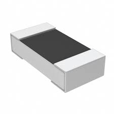
How does a chip resistor work in electronics?
A chip resistor turns electrical energy into heat in a controlled way, creating a predictable voltage drop. In analog paths it sets gains and biases. In digital paths it pulls lines high or low, terminates cables, and matches impedance near connectors and switches to reduce reflections and noise.
Key specifications that matter
• Resistance and tolerance: Select a nominal value from E24, E96, or E192 series. Tighter tolerances improve accuracy in precision controllers and sensor interfaces.
• Power rating and thermal: Ensure the part’s power (I²R or V²/R) includes margin. Derate with temperature and provide copper area for heat spreading.
• Temperature coefficient (TCR): Choose low TCR parts for stable readings over thermal swings, especially around LEDs, capacitors, and timing networks.
• Package size: 0402 and 0603 suit dense laptops and handheld tools, while 0805 and 1206 offer better thermal handling. Match footprint to assembly grips and pick-and-place capability.
• Film technology: Thick film is robust and economical. Thin film provides low noise, precision, and better stability for measurement sensors and microprocessors.
• Voltage rating and surge: Check maximum working voltage and surge capability, especially near fuses, contactors, and inductive lines that can spike.
• Reliability and safety: Look for AEC-Q200 or relevant approvals when circuits interface with industrial panels, long cables, or harsh oils and dust.
How to choose a chip resistor for controllers and microcontrollers
Selecting a Chip Resistor starts with the job it performs, the environment it faces, and the interfaces it touches.
Signal paths for sensors, LEDs, and connectors
• Sensor bridges and references need low TCR and tight tolerance to limit drift.
• LED current setting prefers stable power rating with adequate copper for heat.
• High-speed links near connectors benefit from controlled impedance and short traces to avoid ringing and EMI.
Power paths with fuses, switches, and contactors
• Inrush limiters and bleeders need higher power ratings and safe voltage headroom.
• Sense resistors in controllers should use low-ohmic values with suitable pads for low thermal resistance.
• Circuits that trigger contactors or switch inductive loads need parts with surge resilience and proper spacing.
Layout, soldering, and thermal practices
• Keep traces short between the Chip Resistor and the device pin to reduce noise pickup on microcontroller and microprocessor lines.
• Balance pad sizes and keep symmetry to prevent tombstoning; follow the package maker’s land pattern.
• Use thermal pads or extra copper where power is higher; avoid concentrating heat near sensitive capacitors or crystals.
• Place pull-ups and terminations at the correct end of the trace, typically close to the receiver or connector.
• Prevent contamination from flux residues or oils that can cause leakage paths at high impedance nodes.
• For arrays, route return paths cleanly and separate analog and digital grounds to protect precision sensors.
Materials, noise, and stability considerations
• Thick film resistors suit general controllers, GPIO pulls, and LED indicators with moderate accuracy needs.
• Thin film resistors are ideal for low-noise amplifiers, ADC references, and precision feedback networks.
• Metal element current-sense parts handle higher power with low resistance; check their thermal EMF if you measure microvolts.
• Pay attention to current noise in high impedance stages and match the film choice to the bandwidth you require.
Interfacing across cables and mixed systems
• Long cables introduce capacitance and inductance that can distort edges; series resistors near drivers tame overshoot.
• Use RC snubbers or damping where harnesses exit enclosures through connectors to control EMI and protect safety-critical paths.
• For control cabinets, coordinate resistor choices with fuses, switches, and protective devices so faults clear cleanly without overstress.
Typical applications across laptops, tools, and industrial control
• Laptops: Pull-ups, battery sense, backlight LED current setting, and precision reference dividers for power rails.
• Handheld tools: Debounce and filter around switches, plus rugged terminations for accessory cables.
• Industrial control: Input conditioning for sensors, contactor coil suppression networks, and feedback loops in motor controllers.
• Lighting: LED strings with stable current-set resistors and thermal margin against enclosure heat.
• Measurement: Divider chains for ADCs using thin film types with low TCR to ensure accuracy over temperature.
Selecting values and tolerances with confidence
• Start from the required transfer function, then compute R from target voltage or current.
• Simulate worst case by combining tolerance and temperature effects; keep drift within your calibration budget.
• Ensure the power rating is comfortable at maximum ambient, not just at room temperature.
• When in doubt, step up one package size to gain thermal and soldering robustness without sacrificing density.
Practical tips for assembly and inspection
• Store reels in controlled humidity and avoid touching pads with bare hands; moisture and oils reduce solder quality.
• Verify reflow profiles meet the resistor’s curve to prevent microcracks.
• Inspect for solder fillet quality and check that silkscreen or solder mask does not crowd pads.
• Use calibrated grips on placement equipment and confirm vacuum pick points for very small packages.
Future-ready choices for scalable designs
• Standardize on a short list of E96 values across 0402, 0603, and 0805 to simplify sourcing.
• Prefer low TCR thin film for reference paths and keep thick film for general logic pulls to balance cost and performance.
• Document derating rules, acceptable pad geometries, and inspection criteria so new variants inherit reliable behavior.
Quick specification checklist
• Resistance value and tolerance match the function.
• Power rating and thermal margin verified at peak conditions.
• TCR and material suit precision needs.
• Package size aligns with assembly capability and space.
• Voltage rating and surge capacity are adequate.
• Reliability and safety marks fit the environment and lifecycle.
With the right Chip Resistor choice, circuits remain predictable, sensors stay accurate, and interfaces through connectors and cables operate cleanly. Careful attention to thermal design, layout discipline, and verified specifications gives robust performance across controllers, microcontrollers, laptops, and industrial systems.


